Last time, we introduced a method for adjusting the misalignment of workpieces facing the same direction but separated from a reference position.
This time, we will consider countermeasures for the misalignment that occurs when rotating the robot hand to match the workpiece while the workpiece is rotating.

This time, we will consider countermeasures for the misalignment that occurs when rotating the robot hand to match the workpiece while the workpiece is rotating.
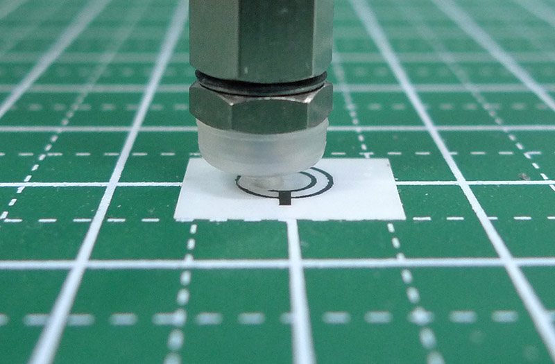
Even if you carefully set the tool frame with the tool tip as the origin, some discrepancy will inevitably occur when picking up a rotated workpiece.
That’s where the ADJ_OFS (Adjust Offset) command comes in handy. This article will explain how to use ADJ_OFS.
Step 1. Rotate the workpiece 180 degrees and run the same program as before.
Step 2. Investigate the amount of deviation and correct it using ADJ_OFS.
After investigating the amount of deviation, it was roughly as shown in the following diagram (based on visual estimation).
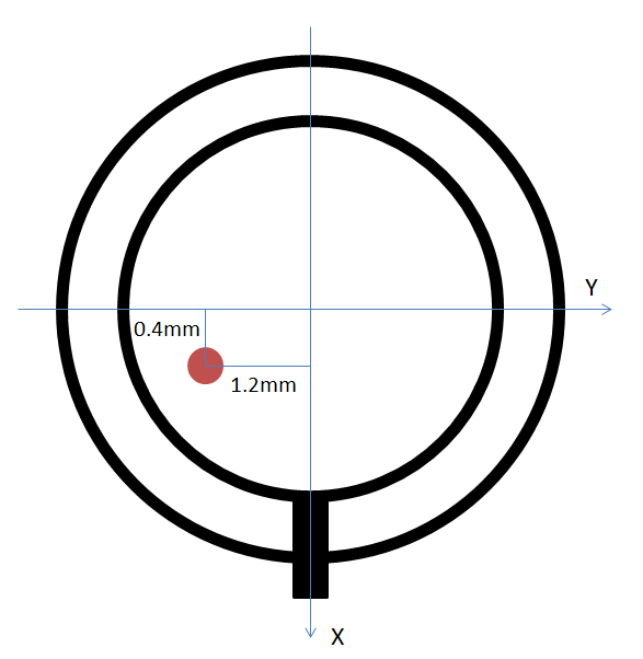
The red circle represents the center of the gripper, and the misalignment is such that shifting it by -0.4 mm in the X direction and +1.2 mm in the Y direction will bring it back to its intended center. ADJ_OFS seems to be responsible for correcting the center of the eccentric circle, so we set it to half the misalignment amount.
In this case, X becomes -0.2 mm and Y becomes +0.6 mm.
Now let’s add the correction statement to the program.
! Move to standby position
J P[1] 100% FINE ;
! Register a position that does not interfere with image capture
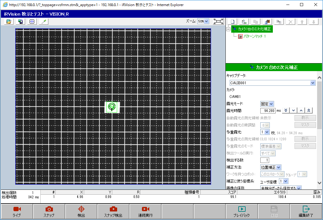
! Vision detection
VISION RUN_FIND 'VISION_R' ;
! Replace with your own vision process name
VISION GET_OFFSET 'VISION_R' VR[1] JMP LBL[999] ;
!ADJ_OFS for fine-tuning rotation
PR[7,1:ADJ_OFS_Val]=(-.2) ;
PR[7,2:ADJ_OFS_Val]=.6 ;
PR[7,3:ADJ_OFS_Val]=0 ;
PR[7,4:ADJ_OFS_Val]=0 ;
PR[7,5:ADJ_OFS_Val]=0 ;
PR[7,6:ADJ_OFS_Val]=0 ;
CALL ADJ_OFS(1,1,7,1) ;
! Move above workpiece
! 30 mm above in Z, 0 for others
PR[8,1:Approach Ofs]=0 ;
PR[8,2:Approach Ofs]=0 ;
PR[8,3:Approach Ofs]=30 ;
PR[8,4:Approach Ofs]=0 ;
PR[8,5:Approach Ofs]=0 ;
PR[8,6:Approach Ofs]=0 ;
L PR[41:Work Ref Pos] 100mm/sec FINE VIS_OFFSET,VR[1] TOOL_OFFSET,PR[8:Approach Ofs] ;
! Move to workpiece
L PR[41:Work Ref Pos] 100mm/sec FINE VIS_OFFSET,VR[1] ;
END ;
LBL[999] ;
! Workpiece not detected
END ;ADJ_OFS() requires an option from “Vision Support Tools (J873)”.
Brief explanation of ADJ_OFS(argument1, argument2, argument3, argument4)
Argument 1: The type of register containing the correction data. Vision register is 1, Position register is 2.
Argument 2: The register number of argument1.
Argument 3: Position register number containing the adjustment amount setting.
Argument 4: Vision register or Ichi register number where the correction data will be stored.
See the manual for more details.
Next, run this program and adjust the values little by little, trying multiple times until you find the correct setting. Also, try different workpiece orientations, such as 90 degrees, not just 180 degrees, to find the correct setting.
If you still can’t get it right, you can try different ADJ_OFS correction values depending on the detection angle. Also, consider eliminating factors that cause misalignment, such as eliminating play in the hand (backlash removal) or positional shifts caused by tension in the mounting cables.
コメント